Using SPM’s Display tool
SPM’s Display tool performs a very basic function: it shows you a three-panel view of a single MRI volume. This can give useful information about an image (such as the values at each voxel, and some header information), and also allows you to overlay some basic statistical maps and check image orientation.
Selecting and displaying an image
- Click the “Display” button in SPM.
- Select a single 3D image. Click done.
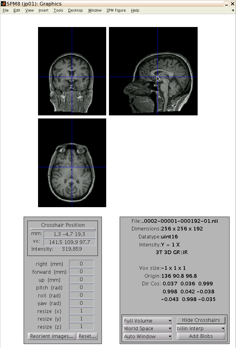
SPM’s Display tool. The image is displayed in three orientations at top, along with crosshairs showing the current voxel. The crosshair position is shown in both mm and voxels at the lower left, as well as the value at the currently-selected voxel (“intensity”; in this case, 319.859). Below this are the 9 parameters that can be adjusted to reorient the image (see below). The bottom right panel shows some information taken from the image header, including dimensions, data type, scaling, and voxel size. You can enter coordinates in mm or voxels in the upper left to go to that location, or click on the thin bar above the coordinate boxes to go to the origin (i.e., [0 0 0]).
Using Display to reorient an image
Perhaps the most common use for reorienting images in SPM is to roughly align structural images with standard space prior to tissue class segmentation. Because the algorithm needs to figure out how to normalize each subject’s brain to standard space, providing a reasonable starting estimate is helpful (e.g., if you want to get to Carnegie Hall, it’s easier to start from Times Square than from Tokyo).
- Select and display the image you want to reorient. (If you are trying to roughly match orientation to a template, you may want to open up a second instance of SPM and display the template alongside, to give you a general idea of the angle.)
- There are 9 parameters that can be adjusted, corresponding to translations and rotations around the 3 major axes, and resizing in the X, Y, or Z plane. In this case we don’t want to change the shape or size of the brain, only how it’s oriented in space, so we’ll stick to the 3 translations (X, Y, Z: in mm) and 3 rotations (pitch, roll, yaw: in radians). Eventually, you want the origin ([0,0,0]) to be close to the anterior commisure, and the overall orientation to match one of the MNI-space templates included with SPM (e.g., SPMPATH/canonical/avg152T1.nii).
- Start by adjusting the pitch, roll, and yaw so that the axes are lined up with the template.
- Now on the image, click on the anterior commisure. Note the coordinate displayed to the left of the image; this tells you how far off you are (and therefore the adjustments that need to be made in the X, Y, and Z direction). For example, if the anterior commisure is at [30, -11, 42], then you would adjust X translations by -30, Y by +11, and Z by -42.
- Click on the anterior commisure again. You should be within a few millimeters of [0,0,0] (it doesn’t have to be perfect).
- Double check the rotations and ensure they still look reasonable. If not, repeat the above steps until image is in alignment with the template.
- Once you are satisfied that the image is reoriented the way you want, it is time to apply these transformations to the image. All of the changes you have made so far are temporarily stored in SPM, but have not been applied to your image. To do so, select “Reorient images”. Select the image you have been working with and click “done”.
- To verify that the reorientation worked, click “Display” again and select the same image. It should now be in the new orientation.
Reorientation works by updating the image header information that describes the voxel-to-world mapping of your image. When you apply the transformations, this header information is updated—which cannot be undone.
Reorienting multiple images
Let’s say that you are conducting an fMRI study, and have realigned your functional images, as well as coregistered the structural image to the mean functional image. This means that, now, all of these images are lined up with each other. But what if for some reason you now want to move the structural image? If you only reorient the structural image, it will no longer be lined up with your functional images. One solution is to apply the transformations to both the structural image, and all of the functional images:
- To start, proceed as above until the structural image is reoriented the way you want.
- After you are satisfied, now select “Reorient images”. But this time, select not only the structural image, but any other images you want similarly updated (in this example, all of the realigned functional images).
Now all of the images you selected will be reoriented using the same parameters, and thus still be properly aligned with each other.
Other display tools
For taking a quick look at an image, sometimes it’s easier to use a command-line tool. If FSL is installed on your system, the fslview command (fslview <imagename>) is convenient, as is mricron (mricron <imagename>).
